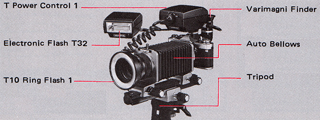
Olympus OM system close-up and macro equipment
T Power Control 1
Introduction
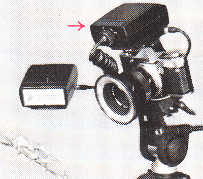
Olympus was the first company to introduce automatic TTL flash control, which allows flash to be used for close-up and macro photography without needing to calculate the additional exposure required by magnification. The T Power Control 1 is used with all 4 of the macro flash units, and provides power for the flash tubes in the T10 Ring Flash 1, T8 Ring Flash 2, T28 Macro Single Flash 1 and the T28 Macro Twin Flash 1.
 |
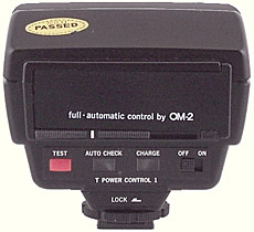 |
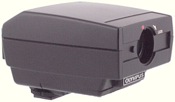
| Olympus OM T Power Control 1 | Rear of Olympus OM T Power Control 1 |
It has the same body as the T32 Electronic Flash, but with the flash tube replaced by a round socket into which the plug from one of the macro flash units can be inserted.
 |
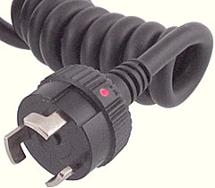 |
| Socket in Olympus OM T Power Control 1 | Plug for Olympus OM T Power Control 1 |
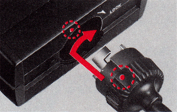
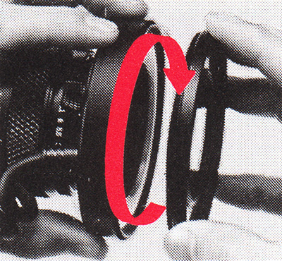
To attach the plug of one of the macro flash units:
- align the red dots on the plug and the Power Control;
- insert the plug;
- turn the plug clockwise until it clicks and locks into place.
To disconnect the plug:
- press and hold the small black button on the front of the Power Control;
- turn the plug anti-clockwise until the red dots are aligned;
- release the button;
- withdraw the plug.
The Power Control works best when used in combination with the TTL automatic exposure control that is incorporated in the OM-2, OM-3 and OM-4 series bodies. By reversing the Calculator Panel, manual exposure with a choice of 2 apertures is available.
The Power Control fits into Accessory Shoe 3 (for the OM-2 camera), Accessory Shoe 4 (for the OM-2N), or the built-in accessory shoe on the OM-2SP, OM-3, OM-3Ti, OM-4 and OM-4Ti. It can also be used on the Power Bounce Grip 2, and connected via a TTL Auto Cord T to the TTL Auto Connector 3 (for the OM-2), the TTL Auto Connector 4 (for the OM-2N), or the built-in connector on the OM-2SP, OM-3, OM-3Ti, OM-4 and OM-4Ti.
The Power Control can use 4 “AA” size 1.5 volt batteries internally, or it can run from the batteries in the Power Bounce Grip 2. Alternatively, it can be powered from the AC Adapter 3 or the AC Adapter 2, with a cable that plugs into a socket above the accessory foot.
When the Power Control was introduced, the only macro flash was the T10 Ring Flash 1, and a calculator panel was supplied for non-automatic flash with the T10 and 50mm lenses (including the Zuiko Auto-Macro 50mm f/3.5). After the other macro flash units were introduced, a page of self-adhesive labels was supplied; these include new distance and aperture scales for the various flash unit/macro lens combinations. There was also a calculator panel for 50mm lenses with the T28 Macro Single Flash 1. For TTL Auto use, the calculator panels for the T32 Electronic Flash can be used.
The Power Control is capable of conventional (non-TTL) automatic flash exposure, using the sensor in the “O” of the Olympus badge, if a calculator panel from a T32 flash is installed. However, this is not likely to work well because the macro flashes and bellows or macro lenses block the sensor, and because the extra exposure required by magnification will not be applied.
| Batteries | 4 × 1.5 volt “AA” cells |
|---|---|
| Length | 104 mm (4.1 inches) |
| Width | 81 mm (3.2 inches) |
| Height | 70 mm (2.8 inches) |
| Weight | 320 gm (11.3 ounces) without batteries |
| US catalog no. | 107-023 |
| Introduced | 1980 |
| Discontinued | 2003 |
Versions
Only one version is known.
Accessories
The Power Control can be powered from external sources; the AC Adapter 3 or the AC Adapter 2. Additional calculator panels were available for the T10 Ring Flash with the Zuiko Auto-1:1 Macro 80mm f/4 and the Zuiko Auto-Macro 135mm f/4.5 lenses.
Use with other equipment
The Power Control with a macro flash head will only provide automatic TTL flash exposure control with the Olympus OM-2, OM-3 and OM-4 series bodies. However, by reversing the Calculator Panel it can be used with other equipment, including other brands, in manual mode. The reversed panel gives a choice of 2 settings, full and ½ power. Exposure will need to be controlled by adjusting the lens aperture, by using a neutral density filter on the lens, or by adding diffusers or neutral density filters to the flash heads.
The Power Control has a standard size accessory foot, but with 2 extra contacts in addition to the central one for a hot shoe. In a suitable Olympus hot shoe, these contacts protrude and mate with contacts in the shoe. In a plain shoe, the extra contacts are retracted and do not make contact with the shoe. It is probably best to avoid shoes from other manufacturers such as Canon and Nikon that also use extra contacts. You must not use the Power Control in a simple metal accessory shoe, because this will make a circuit between the main contact on the base of the foot and the 2 contacts at the side. There are accessories from manufacturers such as Hama that will accept the foot of the Power Control and provide a lead with a standard PC plug.
Some cameras, particularly digital ones, can be damaged by a high flash trigger voltage. The trigger voltage for the Power Control seems to be between 6 and 12 volts.
Instruction manual
Reproduced with permission from the copyright owner, Olympus Optical Co., Ltd
Printed 0381
T Power Control 1
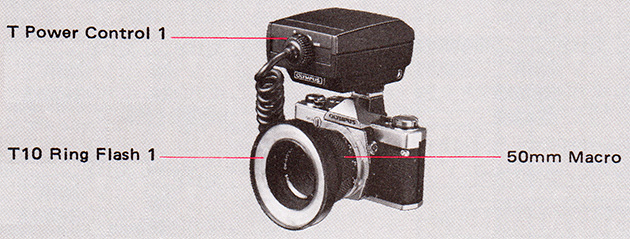
T10 Ring Flash 1
• OPERATING INSTRUCTIONS
The T Power Control 1/T10 Ring Flash 1 combination is specially designed for short working distances where conventional flash units cannot be used. With the OM-2 it extends the advantages of TTL “OTF” Auto flash to the fields of shadowless close-up, medical, scientific and outdoor action macrophotography. Manual flash with the OM-1, OM-10 and cameras other than OM can also be achieved more easily than ever before.
TABLE OF CONTENTS
- Description of Controls
- Loading and Checking the Batteries
- Attaching the T10 Ring Flash 1
- Mounting the T Power Control 1
- Positioning the Calculator Panel/Switching ON the Illuminator
- TTL AUTO Flash with the OM-2N (OM-2)
- Manual Flash with the OM-1 N (OM-1), OM-10 (& Cameras other than OM)
- Flash Photography System Chart
- Main Specifications
- Handling Care
- Medical ZUIKO
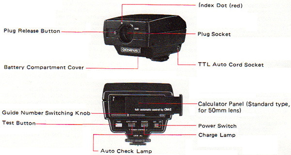
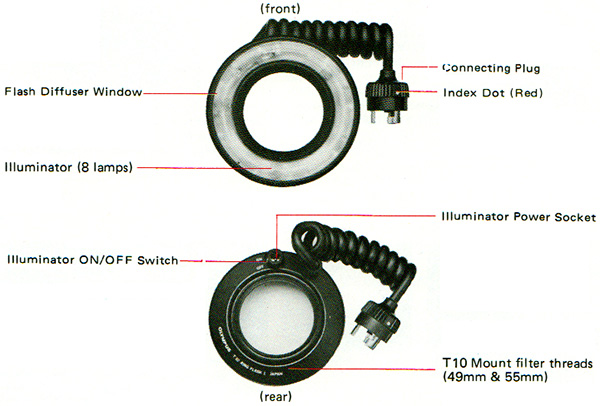
DESCRIPTION OF CONTROLS
T Power Control 1
T10 Ring Flash 1
(1) LOAD THE BATTERIES.
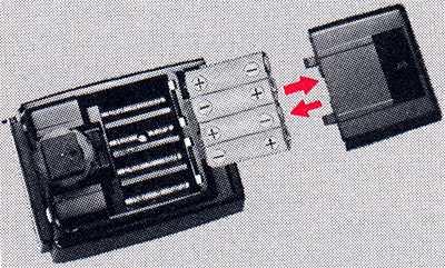
Insert four 1.5V AA, size batteries properly.
Alkaline batteries last about 4 times longer than manganese batteries.
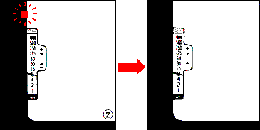
(2) CHECK THE BATTERIES.
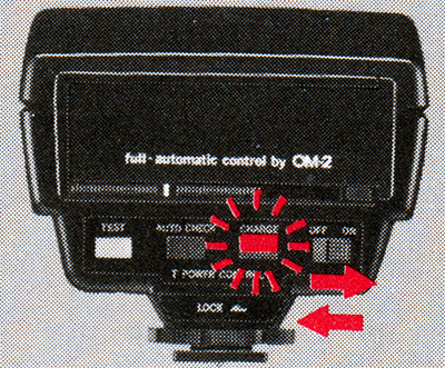
Switch the Power Control ON. Wait until the charge signal lights on. After confirmation, switch the Power Control OFF.
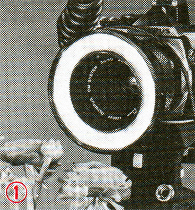
(3) ATTACH THE T10 RING FLASH 1.
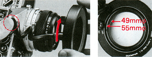
Screw the T10 Ring Flash 1 into the front of the lens.
(4) Connect to the T Power Control 1.
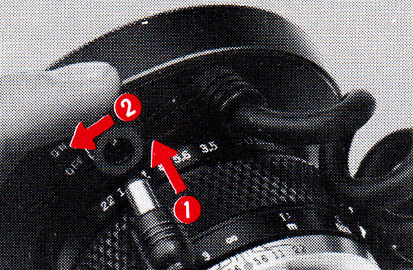
Align red index marks, press and rotate the connecting plug until it stops.
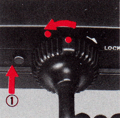
To remove the plug: (1) Press release button (2) Turn plug towards the release button.
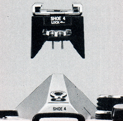
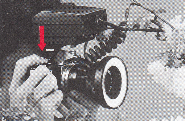
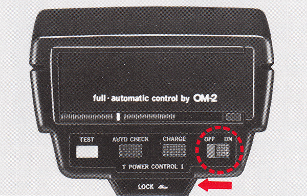
(5) MOUNT THE T POWER CONTROL 1.
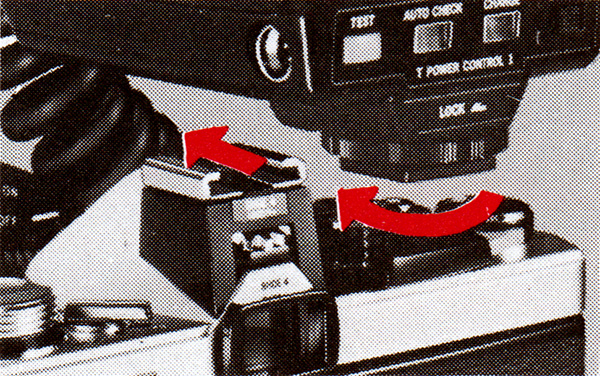
Slide the Power Control into the accessory shoe and turn the lock knob in the direction of the arrow to lock the Power Control in position.
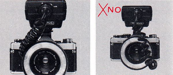
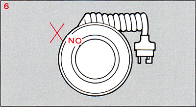
Put the spiral cord away from the flash surface and the aperture scale on the lens.
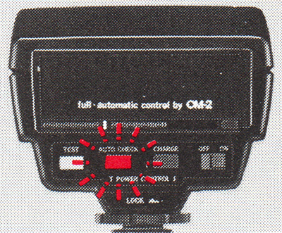
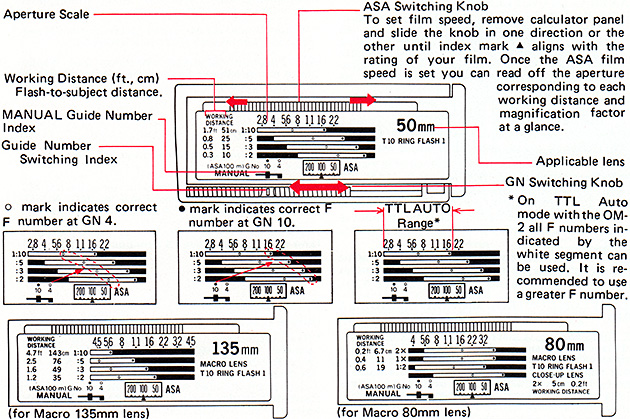
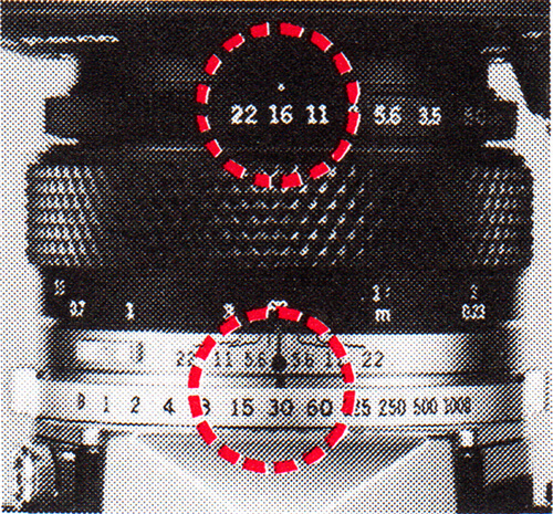
(6) POSITION THE CALCULATOR PANEL.
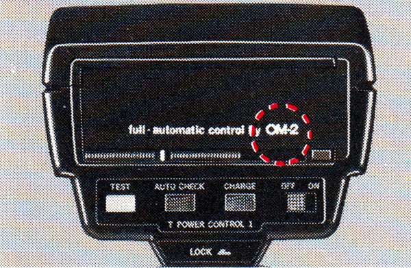
With the calculator panel in the ‘full automatic control by OM-2’ position, the guide number is set automatically to 10 (ASA 100, meters) or 33 (ASA 100, feet).
(7) SWITCH ON THE ILLUMINATOR.
Insert the output plug of the power source and switch on the illuminator.
For composition and focusing with dark subjects (8 lamps).
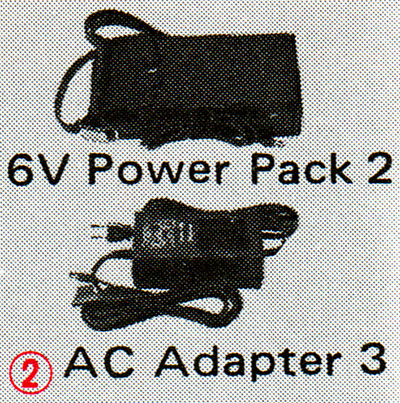
Two optional power sources are available.
TTL CENTRALIZED CONTROL FLASH USING THE RING FLASH AND THE OM-2N (OM-2)
If the identification mark engraved on the top plate of your camera is “OM-2” (and not “OM-2N”), set the synchro terminal to “X” by aligning the red dot on the X and FP selector lever with the “X” indication on the flash socket. Your camera performs TTL Centralized Control Flash with Shoe 3 as described in the following pages, but the charge/auto check indication is not seen in the viewfinder.
PREPARATION
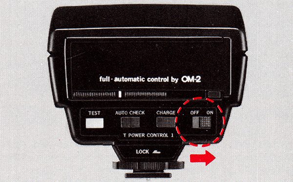
With the calculator panel in the ‘full automatic control by OM-2’ position, turn the power switch to the “ON” position.
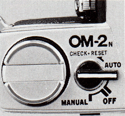
* Set the camera’s selector lever to “AUTO”.
CHECKING THE CHARGE SIGNAL

Wait until the charge signal lights on.
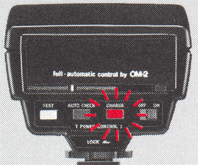
* The charge signal can be seen both in the viewfinder and on the back of the Power Control.
SELECTING THE APERTURE
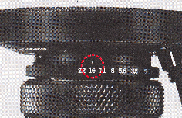
Any aperture can be used for TTL AUTO Flash photography with the OM-2, within the TTL AUTO range. Determine the F stop according to your photographic purpose.
For guidance (ASA 100)
| Lens | Magnification | F stop |
|---|---|---|
| 135mm Macro* | 0.1 × – 0.5 × | F 8 |
| 80mm Macro* | 0.5 × – 2 × | F 32 |
| 50mm Macro | 0.1 × – 0.5 × | F 16 |
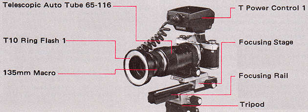
* with Telescopic Auto Tube 65–116 or Auto Bellows
By positioning the calculator panel in reverse and setting it to ‘G. No. 10’ you can read effective aperture range at a glance. See page 23.
TAKING THE PICTURES
Focus and press the shutter release.

(Turn the aperture ring until the meter needle points to 1/30 sec. or slower, and shoot.)
CHECKING CORRECT AUTO FLASH
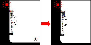
OM-2N
If the signal light blinks repeatedly, the picture was properly exposed by flash.
* The signal light blinks repeatedly also at overexposure, so be sure the subject distance is within the TTL AUTO range shown on the exposure table.
The correct auto flash signal can be seen both in the viewfinder and on the back of the Power Control.
If the signal light goes out, the picture will turn out under-exposed. Choose a larger aperture.
If the signal stays lit (the ring flash did not fire): The subject is bright enough and the picture was taken properly by existing light. The electronic flash was not needed. (In case exposure must be achieved by flash illumination: Turn the aperture ring until the meter needle points to 1/30 sec. or slower, and shoot.)
SHOOTING WITHOUT FLASH LIGHT
If you want to take pictures with existing light, turn the Control Power off; the charge lamp goes out and the ring flash will not fire even when the capacitor is fully charged.
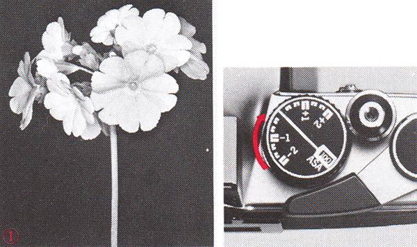
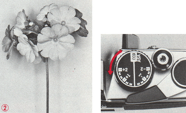
ADVANCED TECHNIQUES
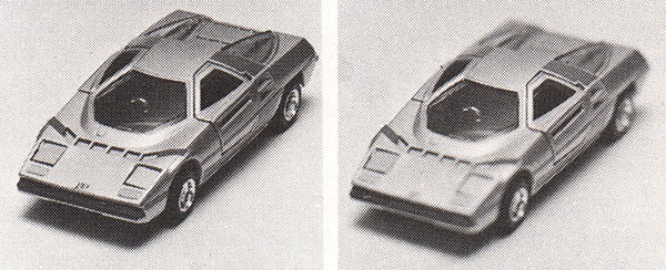
Controlling Depth of Field
 |
|
| at F22 | at maximum aperture |
By stopping your lens down, the zone of acceptable sharpness can be increased.
Flash Exposure Compensation
 |
|
| To compensate dark background | Turn the dial to the (−) side. |
 |
|
| To compensate bright background | Turn the dial to the (+) side. |
RING FILTER POL (optional)
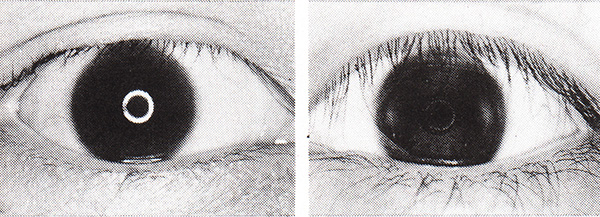 |
|
| Iridology without POL | with POL |
Reflection-reduced flash photography is possible with the cross polarizing filter on TTL AUTO mode.
* Screw into the T10.
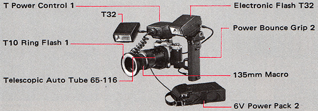
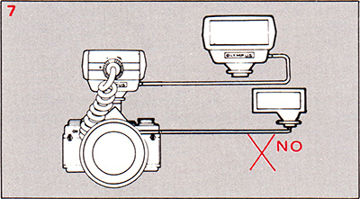
MULTI-UNIT TTL AUTO FLASH

The ring flash unit can be used on TTL AUTO mode together with other T-series flash units for multiple flash effects.
* TTL Auto Multi Connector (optional)
MANUAL FLASH WITH OM-1N (OM-1), OM-10 (& CAMERAS OTHER THAN OM)
- Normally, ultra close-up and macrophotography with manual flash requires complicated calculations for exposure compensation. However, with the use of the calculator panel designed for each macro lens it can be performed with ease.
- Set the camera for flash photography according to the instruction manuals supplied with your camera and Electronic Flash T32 (or T20).
PREPARATION
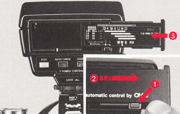
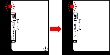
Press the button and remove the calculator panel. (1, 2)
Calculator panels for MC Auto Macro 135 mm F4.5 or MC Auto 1:1 Macro 80 mm F4 are available optionally.

Set the ASA film speed. Slide the calculator panel to the left as far as it will go, until it clicks into place. (3)
CALCULATOR PANEL
The standard type (for 50mm lenses) comes equipped with the T Power Control 1.
MANUAL FLASH
- Determine the working distance (flash-to-subject) or magnification factor.
- Find the working distance or magnification factor (on the exposure table) which is nearest to the value you have determined.
- Read the F number (any in-between value) off the aperture scale positioned at the right of the W.D. or magnification factor, indicated by 0 or o.
- Set the lens aperture at the F number.
- Switch ON the Power Control unit.
- Fine-focus and press the shutter release after the charge signal begins to glow.
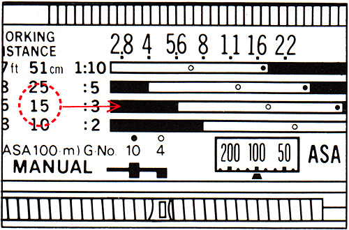
[Example]
Lens: MC Macro 50mm F3.5
W.D.: 17 cm
(ASA 100)
- The aperture scale (3rd from above) corresponding to ‘W.D. 15 cm’ is applicable.
- GN 10 setting cannot be used as • mark indicates beyond ‘F22’ which is not available on the lens.
- The correct F number is ‘16’ indicated by 0.
- Set the GN switching knob to ‘4’ and the lens aperture to ‘16’
* At the GN 4 setting the signal light blinks repeatedly to show that low power output has been emitted.
* For more detailed exposure table, refer to MANUAL FOR MACROPHOTOGRAPHY.
Set the selected F number on the camera lens and the shutter speed to 1/30 sec.
COMBINATION EXAMPLES
With 50mm Macro
Fine-focusing
Multi-unit Flash (1)
Multi-unit Flash (2)
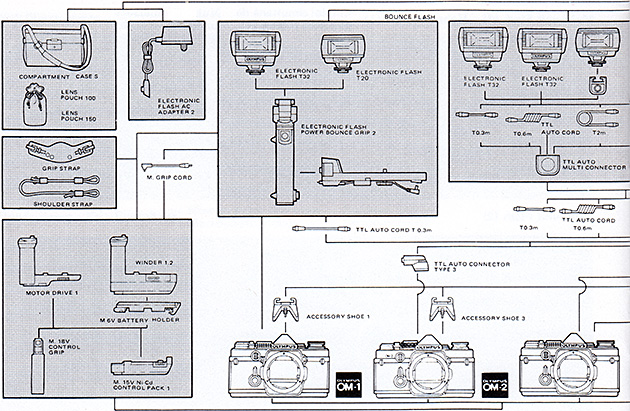
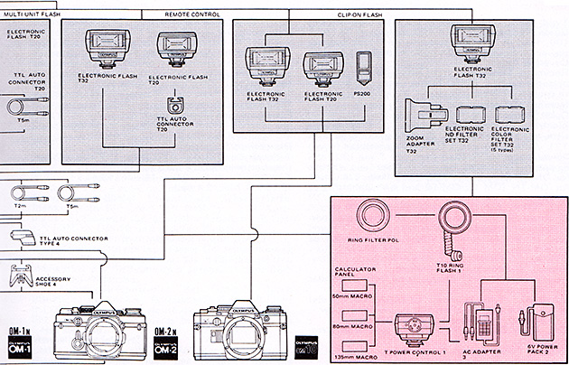
FLASH PHOTOGRAPHY SYSTEM CHART
MAIN SPECIFICATIONS (T Power Control 1 + T10 Ring Flash 1)
Type: Series-circuit type TTL Centralized Control.
Guide Number: 10 (ASA 100, meters) or 33 (ASA 100, feet) at 1 m flash-to-subject distance and full power flash. Low – 4 (ASA 100, m) or 13 (ft.)
Coverage Angle: 80°
Recycling Time: 0.2 – 10 sec. with AA Alkaline batteries on TTL AUTO (varies depending on flash-to-subject distance).
Number of Flashes: 100 – 500.
Color Temperature: 5,800° K.
Electrical Contact with Camera: (1) Clip-on type with hot shoe and lock. (2) Off-camera type with TTL Auto Cord and TTL Auto Connector (w/wo Power Bounce Grip 2).
Exposure Calculator: Reversible plate type – blank for OM-2N (OM-2) for TTL Auto flash; calculator for OM-1N (OM-1), OM-10 and non-OM cameras for Manual flash.
TTL “OTF” AUTO (with OM-2N or OM-2):
Aperture Setting: Continuous, couples with aperture ring setting of camera lens.
SBC Sensor Acceptance Angle: Matches view of camera lens.
TTL AUTO Check: Neon-flicker indication. Viewfinder indication contact provided.
Ready Light Cheek: Charge lamp and viewfinder indication contact.
MANUAL: Guide Number: 10 (ASA 100, meters) or 33 (ASA 100, feet) on full power flash. Low – 4 (ASA 100 meters) or 13 (ASA 100, feet).
TTL Auto Cord Socket: Plug-in type with automatic lock.
External Power Socket: Plug-in type.
Power Source: (1) 1.5V “AA” battery × 4 (incl. NiCd) inside T Power Control 1. (2) 1.5V “C” battery × 4 (incl. NiCd) inside Power Bounce Grip 2. (3) AC house current via Electronic Flash AC Adapter 3. (2) and (3) are activated by on/off switch of power-control unit.
Illuminators: Eight electric bulbs are built into the front of ring flash unit. (Power source: 6V Power Pack 2 or AC Adapter 3).
Recommended Macro Lenses:
MC Macro 135mm F4.5, MC 1:1 Macro 8Omm F4, MC Macro 50mm F3.5
Dimensions & Weight: T Power Control 1 – 81 × 70 × 104 mm, 320 gr. (less batteries) (3.2 × 2.8 × 4.1 in., 11.3 oz.)
T10 Ring Flash 1 – 86∅ × 18 mm, 95 gr. (3.1∅ × 0.7 in., 3.4 oz.)
HANDLING CARE
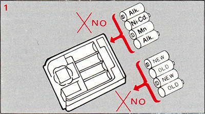
Replace all four batteries at the same time with new batteries.
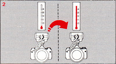
Condensation due to sudden movement from a low to a high temperature area can prevent the flash from firing.
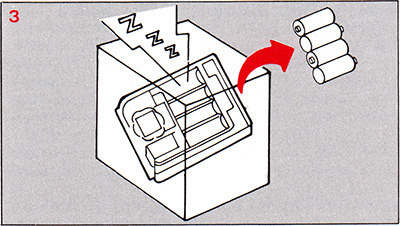
When the flash is not to be used for a long period of time, remove the batteries to prevent leakage.
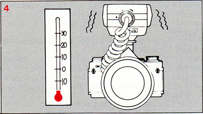
At sub-zero temperature, the batteries will not function normally. So warm them sufficiently before use.
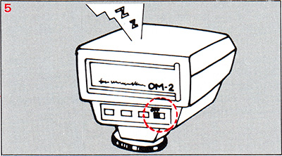
Leaving the switch ON shortens battery life.
If illumination bulbs burn out, have them replaced by an authorized Olympus service center. NEVER try to do it yourself.
Do not use with flash units other than the T32 (or T20).
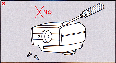
Have repairs performed by an authorized Olympus service center. Dismantling a flash unit involves a hazard.
- As the color temperature of the ring flash is similar to that of daylight, use daylight color films.
- At the working distance of over 2 m (0.7 ft.) the picture edges may darken (with MC Auto Macro 135mm F4.5 and 50mm F3.5).
- The ring flash can be used with ZUIKO 35 mm F2.8, 50mm F1.8, 50mm F1.4, 85mm F2, 100mm F2.8, 135mm F3.5 and 135mm F2.8 lenses. The picture edges may darken if the working distance exceeds the closeup range.
- In TTL AUTO flash operation, use Accessory Shoe 3 when combining the Power Control with the OM-2 (not OM-2N). In MANUAL with the same combination, set the shutter speed at 1/30 sec. or slower.
- Do not exert stronger force upon the Power Control than it needs, when it is attached to or detached from the camera.
- Do not hit the flash unit and do not let it strike any hard object.
- Do not leave the unit in places with temperature over 122°F (50°C), or high humidity.
- The ring flash may cause “redeye” effect to occur in portraits.
- For multiple manual flash, set each G.N switching knob to “10”
- If cleaning is necessary, wipe the units with a soft cloth only.
- The Lens Pouch 150 can accommodate the T Power Control 1.
- Do not overtighten the T10 (or POL) when a filter has been mounted on the lens.
- The ring flash equipment does not feature explosion-free construction. Never use it in the presence of flammable gas.
MEDICAL ZUIKO
Medical close-up and macrophotography conventionally require sophisticated and complicated techniques involving difficult exposure calculations, unwieldy equipment and undesirable directly reflect light. However, this form of photography can now be accomplished in the TTL “OTF” AUTO mode accurately and easily merely by pressing the shutter release, when Olympus ring flash equipment is used.
MAIN FEATURES OF MEDICAL ZUIKO
1. Accurate and easy autoflash exposure
The OM-2’s electronic brain centrally controls all exposure data to do away with complicated calculations. It automatically shuts off the ring flash emission when the correct amount of light has reached the film surface.
2. Continuously variable magnification
By sliding the Telescopic Auto Tube 65–116, changes in magnification can be monitored continuously in the viewfinder.
3. Convenient working distance even for high image magnifications
The MC Auto Macro 135 mm lens features long working distances 37cm (14.6″) – ∞ enabling the photographer to take enlarged images of a lesion without interrupting surgical procedures. The MC Auto 1:1 80 mm Macro is designed to provide optimum resolution at life size.
4. Although the Macro 135 mm has a maximum speed of F4.5, it allows full-open aperture viewing as bright as F4 to facilitate focusing and composition.
5. Ring Filter POL
With the aid of the cross polarizing filter POL, the ring flash reproduces glossy surface objects, reducing undesirable annular light reflection.
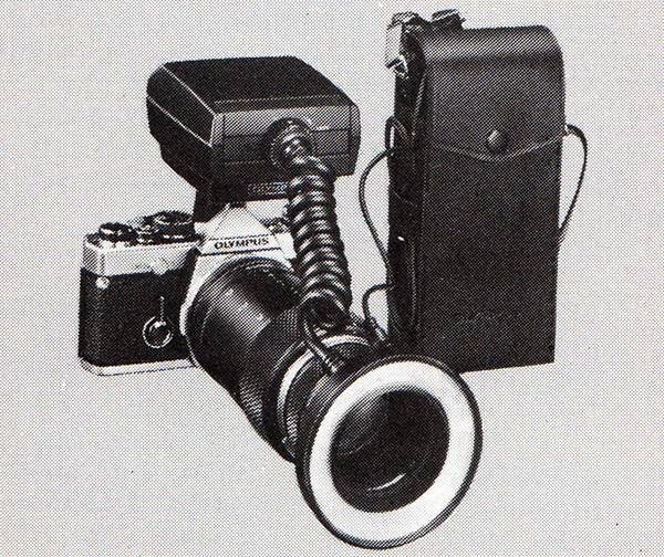
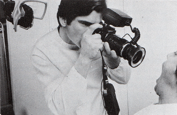
6. Hand-held functionality
The compact and convenient design of the equipment ensures mobility not only for medical, but also for outdoor action photography.
7. Choice of power sources
The ring flash operates off batteries (inside the T Power Control 1 which is mounted to the camera, or a 6 V Power Pack attached to the waist) or the AC Adapter 3.
8. Wide range of applications
Together with other modular OM System components, ring flash is useful in a wide variety of photographic situations (Recordata Back, Winder, etc.).
Cautions
- The ring flash equipment does not feature explosion-free construction. NEVER use it in the presence of flammable gas.
- To prevent overheating, do not cover the AC Adapter 3 with a cloth, etc.
- Depending on the film used, the Ring Filter POL can cause a slight change in coloration (gold tends to turn out bluish; and red, bright red).
- The POL cuts down light by 3 – 6 stops, so open up the lens aperture accordingly to compensate for the light loss.
Exploded parts diagram
Send comments or questions to Alan Wood
![]()
Created 18th May 2001 — Updated 28th February 2021
Copyright © 2001–2021 Alan Wood