Olympus OM system close-up and macro equipment
Auto Bellows
Introduction
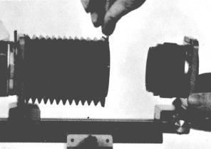
The Olympus bellows unit differs from those of most other 35mm systems because the camera body mount board, not just the lens mount board, can be moved along the rail. This allows the lens mount to be positioned at the end of the rail, so that the rail does not protrude towards the subject. This is particularly important with the high magnifications (and short lens-to-subject distances) that are possible with the 20mm and 38mm bellows macro lenses. The rail can be reversed, allowing the extension to be measured from either the front or the rear.
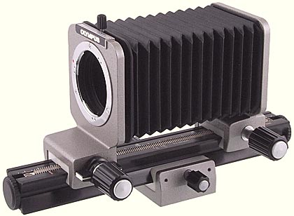
Olympus OM Auto Bellows
The lens mount board and the camera body mount board are moved with a rack and pinion on the top surface of the focusing rail. The focusing tripod block is moved with a rack and pinion on the lower surface of the focusing rail. The boards and the block have a focusing knob on on side, and a clamping knob on the other. The clamping knob can be used to adjust the friction as well as to lock the boards and block in place.
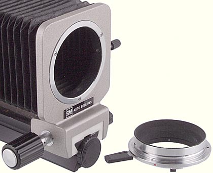
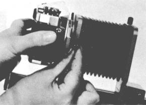
Rear of Olympus OM Auto Bellows
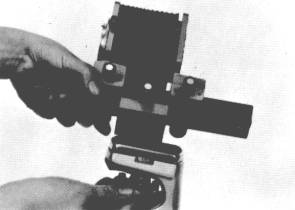
The camera mount can be rotated through more than 180°, and is locked in place with a knob at one side. The mount can be removed, to make it easier to attach the camera body.
The top surface of the focusing rail has an extension scale with white markings on a black background. There are marks at 5mm intervals, and the 50, 100, 150 and 200mm positions are labelled. The top surface also has 1× and 1.5× marks for 50mm and 80mm lenses when used with the slide copier. The 50mm markings are white, the 80mm markings are orange, and the 80mm auto markings (only present on later versions) are green. The Focusing Rail was also available separately.
Another unusual feature is the ability to remove the lens mount and reverse it, allowing the 50mm standard lenses to be reversed for improved performance, with the bellows clamped to the front of the lens instead of to the rear of the lens mount.
The Auto Bellows when used with the 3 original bellows macro lenses permits magnifications from ×0.5 with the Zuiko 1:1 Macro 80mm f/4 lens up to ×12.3 with the Zuiko Macro 20mm f/3.5 lens. With the Zuiko Auto Macro 135mm f/4.5 lens, which was introduced several years later, the focusing range is from infinity to ×1.
| Minimum extension | 36 mm * |
|---|---|
| Maximum extension | 198 mm * |
| Diaphragm coupling | Automatic (with double cable release) |
| US catalog no. | 104-100 |
| Introduced | 1972 |
| Discontinued | 2003 |
* These values are approximate; minor differences in the manufacture of the front standard, rear standard and bellows over the years cause variation of 1–2 mm.
Versions
The Auto Bellows was one of the very first accessories, and some boxes and bellows were made with the original “M SYSTEM” designation that was replaced in January 1973 by the familiar “OM SYSTEM” designation. The “OM SYSTEM” logo is on the rear standard, just below the lens mount.
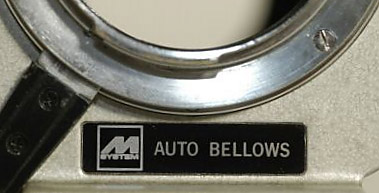
Olympus M System Auto Bellows
Photograph courtesy of Peter and Ingrid Oerlemans (www.secondhandcamera.nl)
There are 2 versions of the rail. The original version, introduced in 1972, includes white 1× and 1.5× marks for 50mm lenses and orange 1× and 1.5× marks for the manual Zuiko 1:1 Macro 80mm f/4 lens in conjunction with the Slide Copier. The later version, introduced in 1980, retains the white marks for 50mm lenses and the orange marks for the manual Zuiko 1:1 Macro 80mm f/4 lens, and additionally has green 1× and 1.5× marks for the Zuiko Auto-1:1 Macro 80mm f/4 lens.
Accessories
The Double Cable Release allows the automatic iris diaphragm mechanism in a lens to operate when the lens is mounted on the bellows, in the normal position or reversed.
In order to mount a lens with a 55mm filter thread in reverse, the Adapter Ring 55→49 mm is needed; this is the same ring that is used to adapt these lenses to the Handy Copy Stand.
In order to mount the Zuiko Macro 20mm f/3.5 or Zuiko Macro 38mm F3.5 bellows macro lenses, the Objective Lens Mount PM-MTob adapter is needed.
The Slide Copier attaches to the bellows and is for making same-size or enlarged copies from mounted slides or from unmounted strips or rolls of film.
The Macrophoto Stand VST-1 with various accessories provides a stable and convenient way of supporting the Auto Bellows when photographing small subjects.
Getting old
There are some reports of the white nylon blocks that clamp onto the rail cracking. They are very expensive to replace as spare parts from Olympus; it would probably be cheaper to buy a complete used bellows unit. The fabric of the bellows can stiffen with age, so that it is no longer possible to use the maximum extension. As with all bellows, there is the possibility of pinholes appearing in the fabric after a lot of use.
Going digital
Some of the Olympus E-series digital SLRs and all of the Canon EOS digital SLRs have a pentaprism that protrudes forwards, and prevents the camera body mount (used with an OM–four-thirds or OM–EOS adapter) from being attached. An Olympus manual or automatic extension tube can be used to provide enough extension to overcome this problem.
| Olympus body | Extension tube | Canon body | Extension tube | |
|---|---|---|---|---|
| E-1 | not needed | EOS 5D MkII | 7 mm | |
| E-3 | 7 mm | EOS 40D | 14 mm | |
| E-300 | not needed | EOS 600D | 14 mm | |
| E-330 | not needed | |||
| E-410 | 7 mm | |||
| E-500 | 7 mm | |||
| E-510 | 7 mm | |||
| E-620 | 7 mm |
As an alternative to using an extension tube on Canon digital SLRs, you can replace the camera mount of the Auto Bellows with a Photomicro Adapter H2. This is very similar to the camera mount, but has a much shorter lever to press to release it from the camera. I do not know if the older Photomicro Adapter H can be used.
Instruction manual
Reproduced with permission from the copyright owner, Olympus Optical Co., Ltd
Printed 0777
INSTRUCTION MANUAL FOR AUTO BELLOWS
In order to fully appreciate the pleasure of macrophotography with the OM body, you have to understand the performances of the Auto Bellows and many additional units compatible with the Bellows, and master their correct usages.
The versatility of the Auto Bellows can become a new means to explore and record the teeming world that lies hidden to the naked eye. This Instruction Manual is written as a guide book to lead you to the exciting and unusual world of macrophotography.
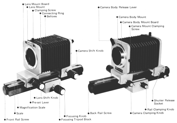
DESCRIPTION OF CONTROLS
SPECIFICATIONS
Camera: OLYMPUS OM System Camera Bodies
Lens Mount: Olympus OM-Mount bayonet (rotation angle 70°).
Lenses: OM System Zuiko lenses
1:1 Macro 80mm F4, Macro 38mm F3.5, Macro 20mm F3.5
(Macro 50mm F3.5; Standard 50mm F1.8, 50mm F1.4, 55mm F 1.2)
Bellows Extension Range:
36mm–198mm (lens in normal position).
56mm–218mm (lens in reversed position).
Graduated focusing rail is 180mm long.
Focusing: Adjustable by focusing knob on the focusing stage with locking device.
Automatic Stop-Down Exposure: Diaphragm linked with shutter by double cable release.
Pre-set lever: Stops diaphragm down to pre-set aperture for previewing depth of field.
Lens Reverse Mounting: Lens and camera mount boards are detachable providing quick reversing of lens.
Focusing Tripod: With provision for mounting on a tripod or on the Macrophoto Stand B adapter.
Focusing Stage: With bellows removed, focusing rail can be mounted.
Dimensions: 74mm (2-15/16″) wide × 132mm (5-3/16″) high × 240mm (9-3/8″) long.
Weight: 930 gr. (32-3/4 oz.).
The Auto Bellows is placed between the OM body and lens to provide the lens extension required in close-up and macrophotographic work. With the double cable release, the diaphragm automatically stops down to the pre-selected aperture at the moment of exposure. The pre-set lever enables you to view the depth of field prior to taking the picture. Since macrophotographs at magnifications greater than 1:1 should be taken with the lens reversed, the Auto Bellows provides a removable lens mounting board. This enables you to reverse the lens without removing the lens from the lens board by extra convenience.
SETTING UP
• Mount the Auto Bellows to a tripod, copy stand, macrophoto stand or other stable support as required.
Mount the Bellows to the support using one of the two sockets located at the base of the focusing tripod block. Use the socket most convenient to your needs taking into consideration the weight with camera and lens, bellows extension required, focal length of lens, etc.
• Attach the camera body to the Auto Bellows.
Loosen the camera mount clamping screw on the Bellows and remove the camera body mount. Attach the camera body mount to the OM body in the same manner as you would attach a standard lens. Mount the camera/camera body mount combination to the Bellows and tighten it in place with the clamping screw.
NOTE: The camera must be mounted to the Bellows before film loading to enable you to properly adjust the needle length of the double cable release.
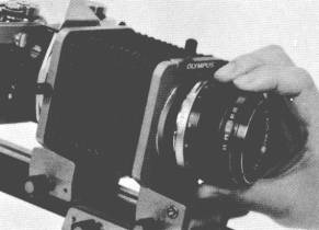
• Attach the lens to the Auto Bellows.
To mount standard lenses or the 1:1 80mm F4 or 50mm F3.5 Macro Lenses, align the red dot on the lens barrel with the red dot on the lens mounting board and turn clockwise until the lens is securely in place.
For the 38mm F3.5 or 20mm F3.5 Macro Lenses, first attach the lens to the Objective Lens Mount PM-MTob. Then, mount the PM-MTob to the Bellows in the same manner you would attach other lenses.
When choosing a lens, take into consideration the subject size, the magnification required, the distance between subject and film, etc. To assist you in selecting the proper lens for your particular needs, see page 35.
ADJUSTING THE DOUBLE CABLE RELEASE (prior to film loading)
• The two needles at the ends of the double cable release must be adjusted before loading film in the camera.
When using standard lenses or the Zuiko Macro Lens 50mm F3.5 with the Auto Bellows, you can retain automatic stop-down exposure operation by using the double cable release. To ensure proper operation, the double cable release must be adjusted to synchronize the actions of the lens diaphragm and camera shutter at the moment of exposure.
In auto bellows operation, the diaphragm blades must close to the pre-selected aperture at the moment the shutter release is triggered. To assure this synchronization, the longer needle length must be adjusted by turning the knurled ring. The longer needle (upper in photo, left) is connected to the lens mount board and the shorter needle (lower) is threaded into the shutter release button on the camera.
Use the following procedure to test the synchronization of the cable release and repeat it until proper operation is assured. (Ascertain that the selector lever of the OM-2 is set at the “MANUAL” position prior to steps below.)
- Set the camera shutter speed ring to the “B” (bulb) position.
- Set the lens aperture ring to the minimum aperture.
- Open the camera back.
- Release the shutter slowly by pressing the plunger on the double cable release.
- Look through the back of the camera. As the shutter opens, the diaphragm blades should close to the preselected aperture.
- Apply additional pressure to the plunger. If the diaphragm blades continue to close, make the needle in the lens mount board longer. Re-test until no further movement of the blades can be seen when the plunger is fully depressed.
• Timer Screw
To take time exposures (over 1 second), first rotate the timer screw counter-clockwise and press the double cable release plunger. Tighten the screw until the plunger remains depressed even after your finger is removed. When the exposure has been completed, loosen the timer screw. The plunger will then return to its original position.
CHOOSING A LENS
• Determine the area to be photographed.
Before choosing the lens, determine the size of the subject area you wish to photograph. For example, if the subject area is 2mm × 3mm, it would be necessary to use the Zuiko Macro Lens 20mm F3.5. If the area were 48mm × 72mm you could use either the Macro Lens 50mm F 3.5 or the 1:1 80mm F4. Also take into consideration the lens-to-subject distance that would best suit your needs, your lighting requirements, the magnification desired, etc.
• Select the lens. (See pages 9-10.)
Zuiko Macro Lenses are specially designed for use with the Auto Bellows. The subject areas covered and magnification ranges for each lens are tabulated below:
| Lens | Subject Area Covered | Magnification Range | |
|---|---|---|---|
| mm | inch | ||
| Zuiko Macro 50mm | infinity(∞) to 48×72 | infinity(∞) to 157/64×253/64 | 1/∞ to 5× (without bellows) |
| Zuiko Macro 80mm | 48×72 to 12×18 | 157/64×253/64 to 15/32×45/64 | .5× to 2× (with bellows) |
| Zuiko Macro 38mm | 13×20 to 4×6 | 33/64×25/32 to 5/32×15/64 | 1.8× to 6× (with bellows) |
| Zuiko Macro 20mm | 5×8 to 2×3 | 13/64×5/16 to 5/64×1/8 | 4.3× to 12× (with bellows) |
When using standard lenses or the Zuiko Macro Lens 50mm F3.5 for photographs at magnifications greater than 1× (life size), best results are achieved by reversing the lens on the Bellows. For optimum sharpness at 1× magnification, however, the Zuiko 1:1 Macro Lens 80mm F4 is recommended.
FOCUSING
• Focusing
In close-up macrophotography, focusing and image size are closely related. If a specific magnification is not required, extend the Bellows until the subject image is approximately the size you desire (the longer the extension, the larger the image size). Then focus by turning the lens shift knob and/or camera shift knob until the image appears sharpest in the camera viewfinder. If you wish to change the image size, extend or retract the Bellows accordingly and re-focus.
If you are shooting at a specific magnification, the amount of bellows extension required for that magnification is constant and therefore you cannot change the position of the lens shift or camera shift knobs. Focusing must be achieved by moving the entire Auto Bellows assembly back and forth until the image is critically sharp. To focus in this manner, turn the focusing knob on the tripod block.
* * *
The reference tables on pages 37 through 40 provide a convenient means of determining the length of bellows extension required for a specific magnification with a given lens. Measure the size of the area to be photographed and refer to the “Subject Area Covered column” in the table. Find the lens you are using in the left-hand column and follow it across the table until it crosses the “Subject Area column” you require. The point where the “Lens column” and “Subject Area column” cross gives you the amount of bellows extension required.
REVERSING THE LENS
To reverse the lens mounted on the Auto Bellows, loosen the Bellows clamping screw on the top of the lens mount board and separate the lens mount board from the connecting ring of the Bellows. Then loosening the front rail screw, remove the lens and lens mount board together from the rail. Reverse and attach the lens on the rail, so that the lens faces the Bellows, then slip the bellows connecting ring over the filter hood of the lens and tighten with clamping screw. Re-attach the front rail screw.
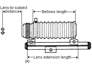
INDICATION OF LENS EXTENSION DISTANCE ON RAIL
 |
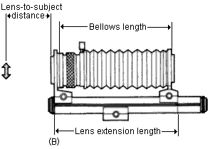 |
The scale engraved on the rail surface is graduated in millimeters. The scale indicates the distance between the extreme ends of the lens mount board and camera body mount (see the pictures above). As the lens mount board comes in contact with the scale end at position “A” (or “B” for the lens reversed), the camera body mount indicates the lens extension distance on the scale in mm. The reference tables on the following pages show the lens extension distances in mm and bellows lengths in cm.
The magnification indexes are engraved on the rail surface for use with the Slide Copier, for which the lens mount board should be aligned to the orange-white line, and the camera body mount will be set at the magnification of the lens in use. To duplicate a 35mm film subject to a 35mm film, set the camera body mount at 1× position, and to duplicate a half frame film subject to a 35mm film, set the camera body mount at 1.5× position.
For easier, accurate focusing, it is recommended to use the Varimagni Finder, Focusing Screens 1-11, 1-12, Eyecup 1 and Dioptric Correction Lenses (see pp. 7-8).
LIGHTING
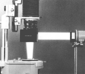
Lighting decisively influences whether your photography will succeed or not. Artificial light, transmitted or reflected, as well as natural light, are available to your macrophotography with the Macrophotography Group that includes many units such as the Trans-illuminator, Epi-illuminators, stands, bases, etc. as schematically explained in page 23.
EXPOSURE ADJUSTMENT

With the Auto Bellows, exposure readings are made by stopping down the lens aperture. First, select a lens opening as desired by turning the aperture ring on the lens. Then stop down the lens aperture by moving the pre-set lever to the vertical position. In case of the OM-1, looking through the viewfinder, rotate the shutter speed ring on the camera until the needle in the finder is centered in the index marks. When the needle aligns properly in the finder, you are ready to take your picture.
NOTE: Be sure to set the shutter speed ring at click-stop positions as no midway settings can be used, and touch up with the aperture ring for fine adjustment, if necessary.
On the other hand, the OM-2 automatically selects the best shutter speed to meet the stopped down aperture.
In manual macrophotography, however, it is sometimes necessary to modify the exposure reading obtained by stop-down measurement, depending on the subject. For subjects against dark backgrounds, stop down the lens by one additional f-stop than indicated by the meter. When the background is light, open the lens by one additional f-stop than indicated by the meter.
It is recommended to use the exposure compensation dial provided on the OM-2 for this adjustment.
In most cases accurate focusing and stopped down lens aperture more than F8 are required for fine macrophotographs because of the extremely small depth of field.
As you get accustomed with the Auto Bellows, you are ready to venture even further into the more exciting world of macrophotography by broadening your abilities with other numerous OM System units.
REFERENCE TABLES FOR AUTO BELLOWS (2)
Zuiko Macro 50mm F3.5
(No Auto Bellows. Green shading indicates the most recommended application range for this lens.)
| Magnification Index engraved on the lens | Image magnification | Distance from film to subject (cm) | Distance from lens to subject (cm) | Subject area covered (mm) | Exposure factor | |
|---|---|---|---|---|---|---|
| Only with Macro 50mm | 1 : 10 | 0.1× | 62.2 | 53.0 | 240×360 | 1.2× |
| 1 : 8 | 0.13× | 51.9 | 42.6 | 192×288 | 1.3× | |
| 1 : 7 | 0.14× | 47.5 | 38.1 | 168×252 | 1.3× | |
| 1 : 6 | 0.17× | 41.1 | 31.6 | 144×216 | 1.4× | |
| 1 : 5 | 0.20× | 36.7 | 27.0 | 120×180 | 1.4× | |
| 1 : 4 | 0.25× | 31.7 | 21.8 | 90×144 | 1.6× | |
| 1 : 3 | 0.33× | 27.0 | 16.6 | 72×108 | 1.8× | |
| 1 : 2.5 | 0.40× | 24.7 | 14.0 | 60×90 | 2.0× | |
| 1 : 2 | 0.50× | 22.6 | 11.4 | 48×72 | 2.3× | |
| With Macro 50mm plus Close-up 49mm f=40cm | 1 : 3 | 0.47× | 22.5 | 11.6 | 51×77 | 2.2× |
| 1 : 2.5 | 0.60× | 20.7 | 9.1 | 40×60 | 2.6× | |
| 1 : 2 | 0.64× | 20.4 | 8.7 | 38×56 | 2.7× | |
| With Macro 50mm plus Extension Tube 25 | 1 : ∞ | 0.49× | 22.9 | 11.8 | 49×73 | 2.2× |
| 1 : 10 | 0.59× | 21.6 | 10.0 | 41×61 | 2.5× | |
| 1 : 8 | 0.62× | 21.4 | 9.6 | 39×58 | 2.6× | |
| 1 : 7 | 0.63× | 21.3 | 9.4 | 38×57 | 2.7× | |
| 1 : 6 | 0.66× | 21.1 | 9.1 | 36×55 | 2.8× | |
| 1 : 5 | 0.69× | 20.9 | 8.7 | 35×52 | 2.9× | |
| 1 : 4 | 0.74× | 20.6 | 8.1 | 32×49 | 3.0× | |
| 1 : 3 | 0.83× | 20.3 | 7.4 | 29×43 | 3.3× | |
| 1 : 2.5 | 0.89× | 20.1 | 6.9 | 27×40 | 3.6× | |
| 1 : 2 | 1.00× | 20.0 | 6.3 | 24×36 | 4× |
For the range outside the shaded area, Zuiko 1:1 Macro 80mm F4 is specially recommended.
Zuiko 1:1 Macro 80mm F4
(Green shading indicate the most recommended application range for this lens.)
| Image magnification | Bellows length (cm) | Lens extension distance (mm) | Distance from film to subject (cm) | Distance from lens to subject (cm) | Subject area covered (mm) | Exposure factor |
|---|---|---|---|---|---|---|
| 0.26 | 3.6 | 68 | 47.4 | 34.7 | 91.2×136.7 | 1.6× |
| 0.3 | 3.8 | 71 | 44.0 | 31.0 | 80.0×120.0 | 1.7× |
| 0.4 | 4.6 | 7.9 | 38.2 | 24.3 | 60.0×90.0 | 2.0× |
| 0.5 | 5.4 | 8.7 | 35.0 | 20.3 | 48.0×72.0 | 2.3× |
| 0.6 | 6.2 | 95 | 33.1 | 17.6 | 40.0×60.0 | 2.6× |
| 0.7 | 7.0 | 103 | 32.0 | 15.7 | 34.3×51.4 | 2.9× |
| 0.8 | 7.8 | 111 | 31.4 | 14.3 | 30.0×45.0 | 3.2× |
| 0.9 | 8.6 | 119 | 31.1 | 13.2 | 26.7×40.0 | 3.6× |
| 1.0 | 9.4 | 127 | 31.0 | 12.3 | 24.0×36.0 | 4.0× |
| 1.2 | 11.0 | 143 | 31.2 | 11.0 | 20.0×30.0 | 4.8× |
| 1.4 | 12.6 | 159 | 31.9 | 10.0 | 17.1×25.7 | 5.8× |
| 1.6 | 14.2 | 175 | 32.8 | 9.3 | 15.0×22.5 | 6.8× |
| 1.8 | 15.8 | 191 | 33.8 | 8.8 | 13.3×20.0 | 7.8× |
| 2.0 | 17.4 | 207 | 35.0 | 8.3 | 12.0×18.0 | 9.0× |
| 2.2 | 19.0 | 223 | 36.2 | 8.0 | 10.9×16.4 | 10.2× |
| 2.3 | 19.8 | 231 | 36.8 | 7.8 | 10.4×15.7 | 10.9× |
For better results, Macro 50mm F3.5 is recommended for image magnifications 0.4 and lower, and Macro 38mm F3.5 for image magnifications 2.2 and higher.
Zuiko Macro 38mm F3.5
(Green shading indicates the most recommended application range for this lens.)
| Image magnification | Bellows length (cm) | Lens extension distance (mm) | Distance from film to subject (cm) | Distance from lens to subject (cm) | Subject area covered (mm) | Exposure factor |
|---|---|---|---|---|---|---|
| 1.8 | 3.8 | 68 | 16.2 | 4.6 | 13.2×19.8 | 7.9× |
| 2.0 | 4.2 | 75 | 16.7 | 4.4 | 12.0×18.0 | 9.0× |
| 2.2 | 5.0 | 83 | 17.3 | 4.3 | 10.9×16.4 | 10.2× |
| 2.4 | 5.8 | 90 | 17.9 | 4.1 | 10.0×15.0 | 11.6× |
| 2.6 | 6.5 | 98 | 18.5 | 4.0 | 9.2×13.8 | 13.0× |
| 2.8 | 7.3 | 106 | 19.2 | 3.9 | 8.6×12.9 | 14.4× |
| 3.0 | 8.0 | 113 | 19.9 | 3.8 | 8.0×12.0 | 16.0× |
| 3.5 | 9.9 | 132 | 21.6 | 3.6 | 6.9×10.3 | 20.3× |
| 4.0 | 11.8 | 151 | 23.3 | 3.5 | 6.0×9.0 | 25.0× |
| 4.5 | 13.7 | 170 | 25.1 | 3.4 | 5.3×8.0 | 30.3× |
| 5.0 | 15.6 | 189 | 27.0 | 3.3 | 4.8×7.2 | 36.0× |
| 5.5 | 17.5 | 208 | 28.8 | 3.2 | 4.4×6.5 | 42.3× |
| 6.0 | 19.4 | 227 | 30.6 | 3.2 | 4.0×6.0 | 49.0× |
| 6.1 | 19.8 | 231 | 31.0 | 3.2 | 3.9×5.9 | 50.4× |
Zuiko Macro 20mm F3.5
(Green shading indicates the most recommended application range for this lens.)
| Image magnification | Bellows length (cm) | Lens extension distance (mm) | Distance from film to subject (cm) | Distance from lens to subject (cm) | Subject area covered (mm) | Exposure factor |
|---|---|---|---|---|---|---|
| 4.3 | 3.6 | 68 | 12.9 | 2.1 | 5.6×8.4 | 27.9× |
| 4.5 | 4.0 | 73 | 13.3 | 2.1 | 5.3×8.0 | 30.3× |
| 5.0 | 5.0 | 8.3 | 14.3 | 2.1 | 4.8×7.2 | 36.0× |
| 5.5 | 6.0 | 93 | 15.2 | 2.0 | 4.4×6.5 | 42.3× |
| 6.0 | 7.0 | 103 | 16.2 | 2.0 | 4.0×6.0 | 49.0× |
| 6.5 | 8.0 | 113 | 17.2 | 2.0 | 3.7×5.5 | 56.3× |
| 7.0 | 9.0 | 123 | 18.2 | 1.9 | 3.4×5.1 | 64.0× |
| 7.5 | 10.0 | 133 | 19.2 | 1.9 | 3.2×4.8 | 72.3× |
| 8.0 | 11.0 | 143 | 20.1 | 1.9 | 3.0×4.5 | 81.0× |
| 8.5 | 12.0 | 153 | 21.1 | 1.9 | 2.8×4.2 | 90.3× |
| 9.0 | 13.0 | 163 | 22.1 | 1.9 | 2.7×4.0 | 100.0× |
| 9.5 | 14.0 | 173 | 23.1 | 1.9 | 2.5×3.8 | 110.3× |
| 10.0 | 15.0 | 183 | 24.1 | 1.9 | 2.4×3.6 | 121.0× |
| 10.5 | 16.0 | 193 | 25.1 | 1.8 | 2.3×3.4 | 132.3× |
| 11.0 | 17.0 | 203 | 26.1 | 1.8 | 2.2×3.3 | 144.0× |
| 11.5 | 18.0 | 213 | 27.1 | 1.8 | 2.1×3.1 | 156.3× |
| 12.0 | 19.0 | 223 | 28.1 | 1.8 | 2.0×3.0 | 169.0× |
| 12.4 | 19.8 | 231 | 28.9 | 1.8 | 1.9×2.9 | 179.2× |
OLYMPUS
OLYMPUS OPTICAL CO., LTD.
43-2 Hatagaya 2-chome, Shibuya-ku, Tokyo, Japan
Exploded parts diagram
Send comments or questions to Alan Wood
![]()
Created 18th May 2001 — Updated 28th February 2021
Copyright © 2001–2021 Alan Wood